
Orange Raspberry Pi Pico Advanced Kit
Orange Raspberry Pi Pico Advanced Kit – In the previous blog, we discussed the installation procedure and a few important topics , and I believe that information will be very useful for you to understand the basics of the raspberry pi pico board.If you haven’t already, please check out that blog.
We will be covering so many new things about the Raspberry Pi Pico board in this blog and I am very excited to talk about those things, and I am pretty sure you will be as well.
So, without any further ado let’s get started.
We have included a few advanced topics in this blog, that is why to simplify the learning process, I have divided this blog into increasing hierarchical sections.
In the first section of this blog, we will go over basic terms like interfacing the PIR sensor and LED with the Raspberry Pi Pico board.
This section will teach you the fundamentals of the raspberry pi pico board’s GPIO section.
Following that, we will discuss the basic ports of the Raspberry Pi Pico board, followed by advanced ports such as I2C and SPI.
So, this is the roadmap of this blog. You can also refer to the booklets that come with this kit.
According to the roadmap, in the next part of the blog, we will learn how to connect the PIR sensor with the Raspberry Pi Pico.
PIR Sensor With The Raspberry Pi Pico
You may have heard of the burglar alarm system. These burglar alarms are programmed to detect motion.
When a moving object passes in front of these systems, they detect it and send high-level signals to the controller.
These sensors are used to detect infrared signals. It has two pyroelectric material slots.
The booklet contains more detailed information about the pyroelectric material. You can learn more about this material by reading the booklet.
pyroelectric material is the type of material that has the ability to produce a certain amount of voltage when heated or cold.
When the surrounding temperature of the material changes the material produces a certain amount of voltage and this changed voltage becomes normal if the previous change in the temperature remains constant. And this is the only reason, we should keep the PIR sensor on for two-three seconds before using it.
Talking about the PIR Sensor, it has two slots made up of this type of material.
After turning on the sensor, both slots detect the same amount of Temperature, which is the ambient amount radiated from the room, walls, or outdoors.
When a warm body, such as a human or animal, passes by, one half of the PIR sensor is intercepted, resulting in a positive differential change between the two halves.
And when the warm body moves away from the sensing area, the sensor produces a negative differential change. These pulses of change are what is detected.
This change in the output then will be given to the controller where the controller executes the required operations based on the input received.
So, this was about the working principle of the PIR sensor. In the next part of the blog, we will talk about the interfacing of the PIR sensor with raspberry pi pico.
Interfacing Of The PIR Sensor With The Raspberry Pi Pico
There are three output pins on the PIR sensor. One of these pins is a signal pin, while the others are power pins.
To use this PIR sensor, we must connect the signal pin of the PIR sensor to any GPIO pin of the Raspberry Pi Pico.
Because the PIR Sensor’s output will be either HIGH or LOW, we won’t need to use any communication ports. The output pin can be connected to any standard GPIO pin. And we can use the normal GPio Read function to read the output of the sensor.
Please see the image below to understand the interfacing diagram.

Python Code For PIR Sensor
So, here is the Python code for communicating with the PIR Sensor.
from machine import Pin
import utime

pir_sensor = Pin(16, Pin.IN)
utime.sleep(2)

while True:
   if pir_sensor.value() == 1:
       print("Motion Detected")
       utime.sleep(3)
   else:
       print("No Motion")
       utime.sleep(1)
utime.sleep(0.1)
In this code, we are instructing the PICO board to read the output and turn on the LED whenever the surrounding temperature changes.
Now you can upload the above code to your raspberry Pi Pico board. If you have any doubts then please mention your doubts in the comment section.
Okay, so this was about connecting the PIR sensor to the Raspberry Pi Pico.
If you have any questions about this section, please leave them in the comments section.
In the following section of this blog, we will learn how to connect the buzzer module to the Raspberry Pi Pico.
Buzzer With The Raspberry Pi Pico
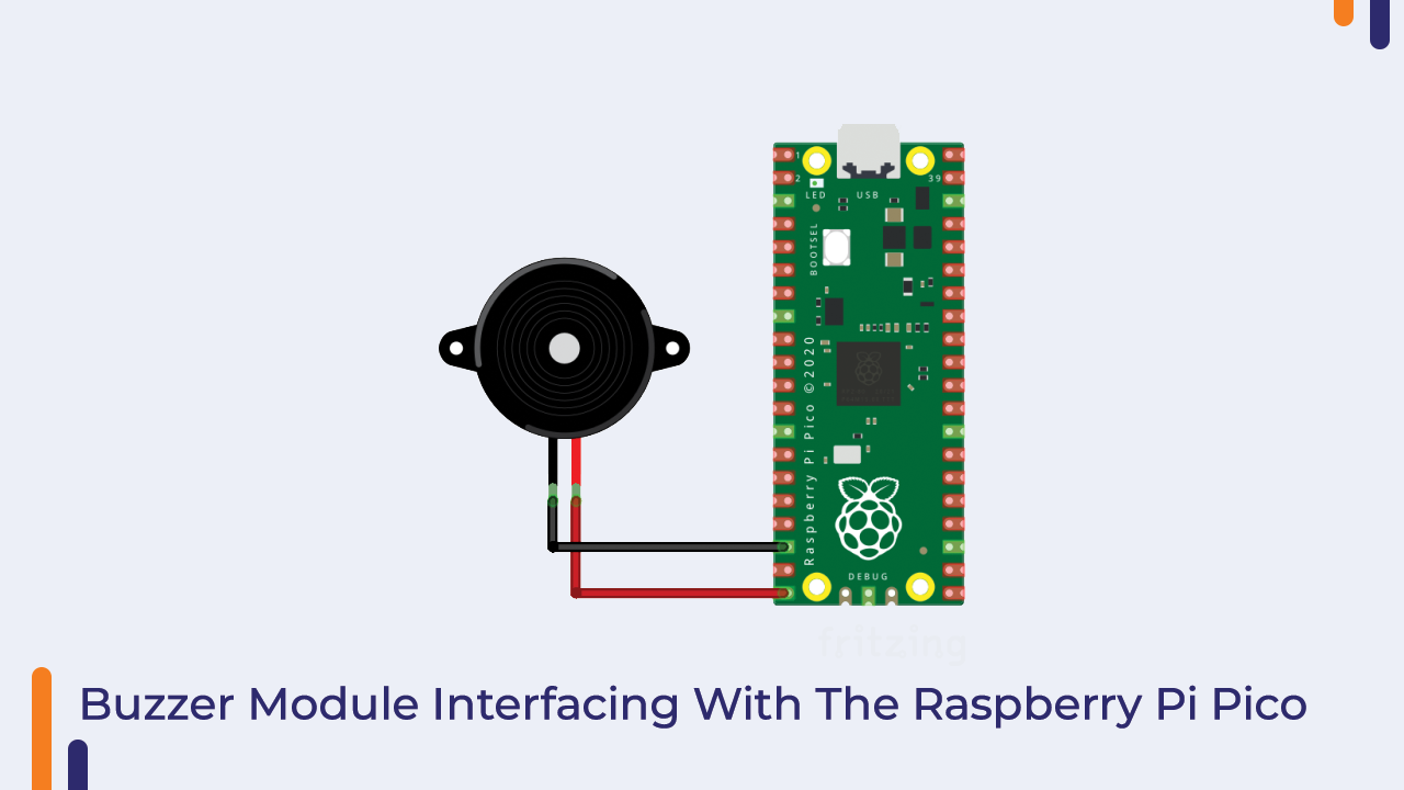
This Orange Raspberry Pi Pico kit includes an active buzzer. As we all know, an active buzzer contains an oscillator that generates sound signals based on the input it receives.
The buzzer module’s interface with the Raspberry Pi Pico is a very simple part. It has two pins, one of which has a negative sign on it and can be connected to the board’s GND pin and the other to any GPIO pin on the Raspberry Pi Pico.
Please refer to the image below and make the connection as shown.
So this was all about connecting the buzzer module to the Raspberry Pi Pico.
Now we’ll get into the coding of the Buzzer module.
Python Code For Active Buzzer Module
from machine import Pin
import time

buzzer = Pin(15, Pin.OUT)

while True:
    buzzer.value(1)
    time.sleep(1)
    buzzer.value(0)
The While loop in the code is used to read the output from the switch. When we press the switch, we get a zero-level output, and when we let go of the pressed switch, we get a high-level signal.
And, based on the input from the switch module, we activate the buzzer module.
So, we learned how to connect the Buzzer module to the Raspberry Pi Pico board in this tutorial.
If you have any comments or questions about this section, please leave them in the section below.
We will learn how to connect the 16 RGB LED to the Raspberry Pi Pico in the following section.
16 RGB LED Ring With The Raspberry Pi Pico
This is a brand-new item included in this kit. We can use the product to create various colour patterns.
It has 16 RGB LED pins that are controlled by only three output pins.
One of these three pins is a data pin, while the other two are power pins.
We can connect the data pin to any GPIO pin on the Raspberry Pi and the power pins to the Raspberry Pi Pico board’s power port.
Please see the image below to better understand the interfacing diagram.

So this is was about the interfacing, Now we’ll get into the coding of the Raspberry Pi Pico.
Python Code For 16 RGB LED Ring
import array, time
from machine import Pin
import rp2

#
############################################
# RP2040 PIO and Pin Configurations
############################################
#
# WS2812 LED Ring Configuration
led_count = 16 # number of LEDs in ring light
PIN_NUM = 13 # pin connected to ring light
brightness = 1.0 # 0.1 = darker, 1.0 = brightest

@rp2.asm_pio(sideset_init=rp2.PIO.OUT_LOW, out_shiftdir=rp2.PIO.SHIFT_LEFT,
             autopull=True, pull_thresh=24) # PIO configuration

# define WS2812 parameters
def ws2812():
    T1 = 2
    T2 = 5
    T3 = 3
    wrap_target()
    label("bitloop")
    out(x, 1)               .side(0)    [T3 - 1]
    jmp(not_x, "do_zero")   .side(1)    [T1 - 1]
    jmp("bitloop")          .side(1)    [T2 - 1]
    label("do_zero")
    nop()                   .side(0)    [T2 - 1]
    wrap()


# Create the StateMachine with the ws2812 program, outputting on pre-defined pin
# at the 8MHz frequency
sm = rp2.StateMachine(0, ws2812, freq=8_000_000, sideset_base=Pin(PIN_NUM))

# Activate the state machine
sm.active(1)

# Range of LEDs stored in an array
ar = array.array("I", [0 for _ in range(led_count)])
#
############################################
# Functions for RGB Coloring
############################################
#
def pixels_show(brightness_input=brightness):
    dimmer_ar = array.array("I", [0 for _ in range(led_count)])
    for ii,cc in enumerate(ar):
        r = int(((cc >> 8) & 0xFF) * brightness_input) # 8-bit red dimmed to brightness
        g = int(((cc >> 16) & 0xFF) * brightness_input) # 8-bit green dimmed to brightness
        b = int((cc & 0xFF) * brightness_input) # 8-bit blue dimmed to brightness
        dimmer_ar[ii] = (g<<16) + (r<<8) + b # 24-bit color dimmed to brightness
    sm.put(dimmer_ar, 8) # update the state machine with new colors
    time.sleep_ms(10)

def pixels_set(i, color):
    ar[i] = (color[1]<<16) + (color[0]<<8) + color[2] # set 24-bit color

def breathing_led(color):
    step = 5
    breath_amps = [ii for ii in range(0,255,step)]
    breath_amps.extend([ii for ii in range(255,-1,-step)])
    for ii in breath_amps:
        for jj in range(len(ar)):
            pixels_set(jj, color) # show all colors
        pixels_show(ii/255)
        time.sleep(0.02)

red = (255,0,0)
green = (0,255,0)
blue = (0,0,255)
yellow = (255,255,0)
cyan = (0,255,255)
white = (255,255,255)
blank = (0,0,0)
colors = [blue,yellow,cyan,red,green,white]

while True: # loop indefinitely
    for color in colors:
        breathing_led(color)
        time.sleep(0.1)
The above code can be used to control the RGB ring. The LEDs of the RGB Ring are turned on in a pattern using the code above. Please use the code and let me know if you run into any issues.
Max7219 8*8 LED Matrix Display With The Raspberry Pi Pico Board
You may have seen 8*8 LED Matrix displays in the market. These displays are primarily used for advertising and a variety of other purposes.
Prior to the invention of the dot matrix display, it was extremely difficult to design a display similar to the dot matrix display.
Back then, in order to create a display similar to a dot matrix display, we had to connect 16 pins to a microcontroller, which was a difficult task.
So, a few curious engineers like you and me stepped forward to solve the problem, and they created the unique design of the dot matrix display by combining a few common electronic technologies like multiplexing.
You’ve probably heard of multiplexing. If not, don’t worry, I’ll let you know.
Assume you’ve been asked to work on an embedded project, but there are some constraints on the pin.
You only have six pins, but your project requires twelve. In that case, you may be thinking that you will use communication protocols, but suppose there are none available on the system.
Isn’t it true that the problem has grown in size? What are your thoughts on a possible solution to this?
Here you can use multiplexing. Multiplexing is a process that is processed by a circuit called a multiplexer.
Multiplexing is the process of combining two or more signals and sending them to an output device. You might think that combining two or more signals would distort the information, but this is not the case.
True, multiple signals are mixed in multiplexing, but guard bands are added between each burst to prevent the signals from being mixed.
So, this is what multiplexing is.
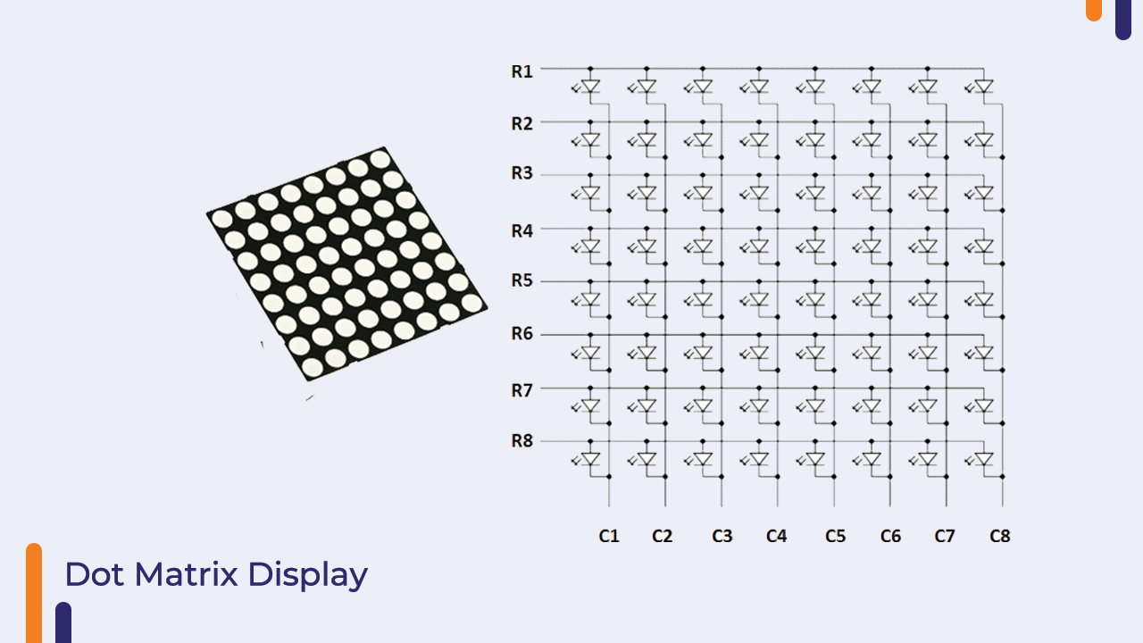
As I told you earlier, the 8*8 dot matrix display also uses the same technique to blink the LEDs.
In the dot matrix display, the LEDs are connected in columns and rows. To turn on any particular led, we will have to power the correct column and row.
The following image will clear all your doubts about the above concept.
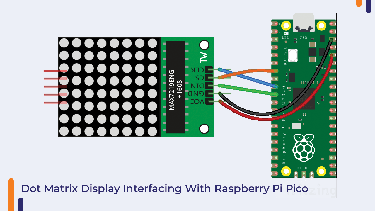
Interfacing The Dot Matrix Display With The Raspberry Pi Pico Board
So, now that you understand the fundamentals of the dot matrix display, we can move on to the display’s interfacing with the Raspberry Pi Pico Board.
In the image below, we have connected the dot-matrix display to the Raspberry Pi Pico. Please look into it.
Python Code For Dot Matrix Display
You can use the Following code, to start working with the Dot Matrix Display.
from machine import Pin, SPI, ADC
import max7219
from utime import sleep

MAX7219_NUM = 4
MAX7219_INVERT = False
MAX7219_SCROLL_DELAY = 0.15
cs_pin = 5

spi = SPI(0)
display = max7219.Matrix8x8(spi=spi, cs=Pin(cs_pin), num=MAX7219_NUM)
display.brightness(2)

p = MAX7219_NUM * 8
to_volts = 3.3 / 65535
temper_sensor = ADC(4)  #Get the voltage value of the temperature sensor from ADC(4)

while True:
   temper_volts = temper_sensor.read_u16() * to_volts  # acquire the temperature depend on it's voltage
   celsius_degrees = 27 - (temper_volts - 0.706) / 0.001721    # Calculated celsius
   text = 'Temp:'+str(round(celsius_degrees,2))   # Take 2 decimal

   for p in range(MAX7219_NUM * 8, len(text) * -8 - 1, -1):
       display.fill(MAX7219_INVERT)
       display.text(text, p, 1, not MAX7219_INVERT)    # Display in the x, y position(string, x, y, color=1)
       display.show()
       sleep(MAX7219_SCROLL_DELAY)
So, In this way, we learned how to connect the dot matrix display to the Raspberry Pi Pico board in this manner.
If you encounter any difficulties, please let us know in the comments section. comment section.
I2C Backpack LCD With The Raspberry Pi Pico Board
We’ve covered the fundamentals up to this point; in this section, we’ll learn how to connect the I2C backpack LCD Backpack to the Raspberry Pi.
There are two kinds of LCDs available on the market (Based on the Interface).
I2C Backpack LCD and normal LCD. The difference between these two LCDs is that a standard LCD requires up to 9-10 pins to interface with any microcontroller, whereas an I2C backpack only requires four pins to establish communication between the LCD and the microcontroller.
In the following image you can see the interfacing of the LCD with the Raspberry Pi Pico.
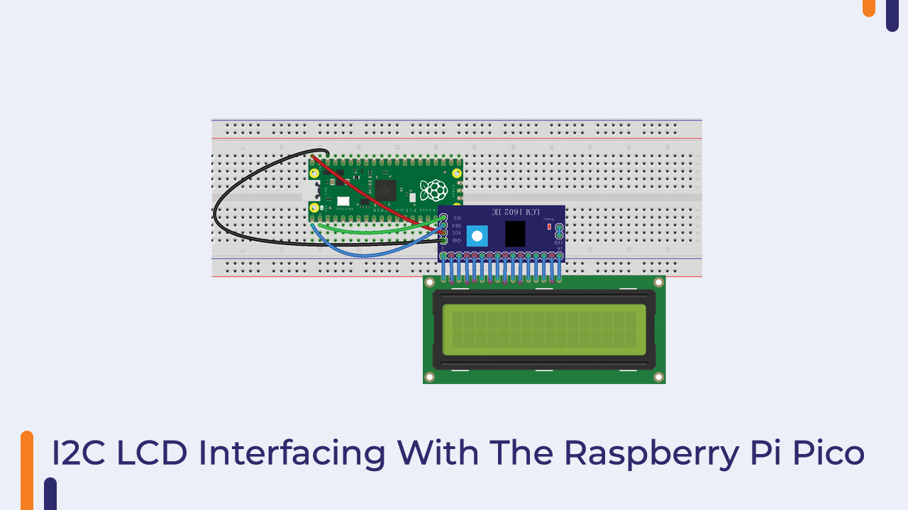
Here, we’ve connected the LCD’s SCL and SDA pins to the Raspberry Pi Pico’s I2C communication port.
Okay, now that our interfacing portion is complete, we can move on to the coding portion.
If you want to learn more about I2C communication, please download the booklet. We went over everything in great detail in that booklet.
Python Code For I2C Backpack LCD
In the preceding code, we are determining the product’s I2C address. Each slave device in I2C communication has a unique I2C address, which is used by the master device to distinguish between two slave devices and send data to the correct slave device.
And if we do not provide the correct I2C address to the controller, the slave device will not receive the necessary information from the microcontroller, which is why determining the correct address becomes necessary.
from machine import I2C, Pin
from time import sleep
from pico_i2c_lcd import I2cLcd
i2c = I2C(0, sda=Pin(0), scl=Pin(1), freq=400000)

I2C_ADDR = i2c.scan()[0]
lcd = I2cLcd(i2c, I2C_ADDR, 2, 16)
while True:
    print(I2C_ADDR)
    lcd.blink_cursor_on()
    lcd.putstr("Orange Kits")
    sleep(2)
    lcd.clear()
    lcd.putstr("Hello From Robu.in")
    sleep(2)
    lcd.clear()
The above code will return the module’s I2C address, which you must enter in the following code.
The above code will display the message “Hello From Robu.in” on the LCD. We have explained everything about the code in the booklet, so please read it if you want to learn more about it.
In the following section of the blog, we will discuss how to interface the servo motor with the Raspberry Pi Pico.
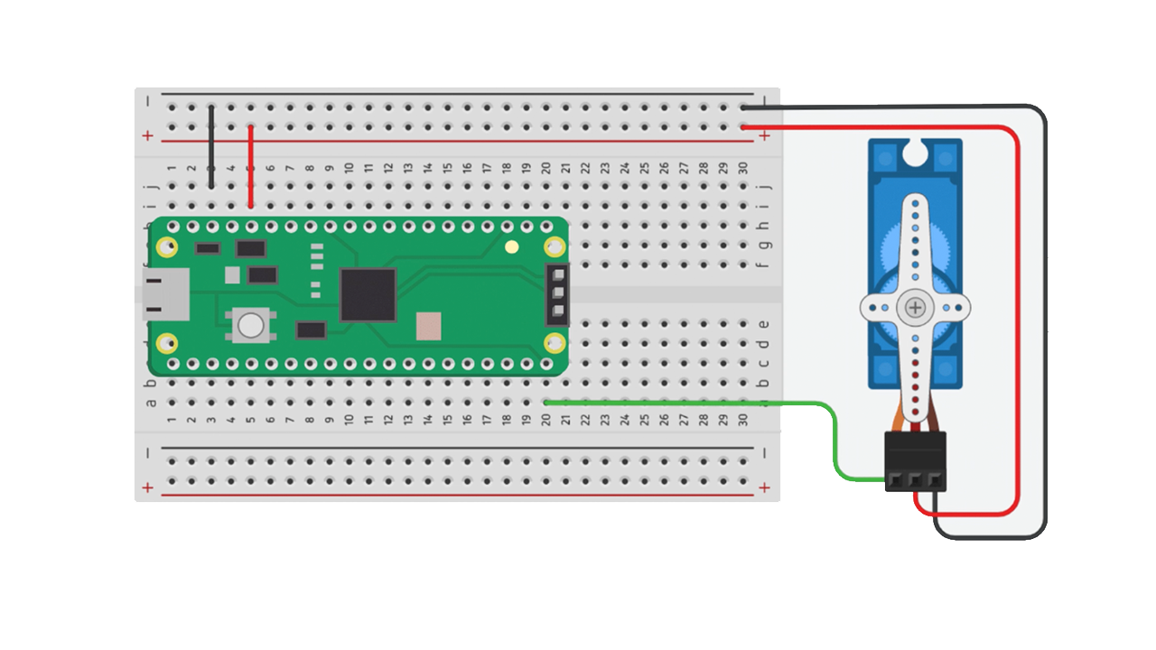
Servo Motor With The Raspberry Pi Pico
We’ve all seen servo motors, which are known for their precise and accurate shaft moment. In this section, we will learn how to connect the servo motor to the Raspberry Pi Pico.
The servo motor is a more powerful version of the DC motor. Yes, you read that correctly! Unlike the DC motor, the construction of the servo motor is the same. The only difference between the servo motor and the DC motor is that the servo motor has an encoder built in, whereas the DC motor requires an external encoder.
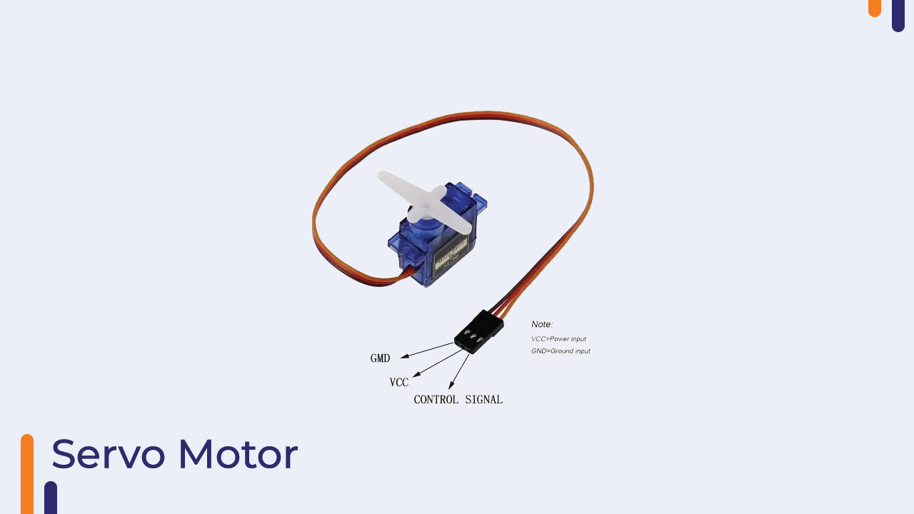
What exactly is an Encoder? The encoder is a device that calculates the rotations of the motor.
There are various types of encoders available on the market, which I have mentioned in the booklet. If you want to learn more about those types, please read the blog’s booklet.
So, that was the basic introduction to the servo motor; in the next section of the blog, we will discuss python code.
Python Code For Controlling The Servo Motor
In the code below, we generate PWM signals to control the servo motor. To control the servo motor, use the code below.
from machine import Pin, PWM

import utime;
Mid = 1500000
Min = 100000
Max = 200000
pwm = PWM(Pin(0))
pwm.freq(50)
Pwm.duty_ns(MID)
while True:
    pwm.duty_ns(Min)
    utime.sleep(1)
    pwm.duty_ns(Min)
    utime.sleep(1)
    pwm.duty_ns(Max)
    utime.sleep(1)
    pwm.duty_ns(Mid)
    utime.sleep(1)
ok So now when you upload the code to the Raspberry Pi Pico board the servo will start spinning.
In the preceding code, we use the machine module to communicate with the servo motor. That machine module is divided into two classes: Pwm and Pin.
We already know how to use the pin class. This class is used to configure the pin’s modes.
In terms of the PWM class, it is used to generate the frequency on a specific pin.
In this case, we’re using this class to generate a 50hz frequency with a delay.
So in this way, we learned how to connect the servo motor to the Raspberry Pi Pico.
If you have any questions about the code, please leave them in the comments section.
Conclusion:
So, we have covered all of the topics of the Orange Raspberry Pi Pico Advance, and we hope that you have learned a few new things from this blog. If you have any questions, please leave them in the comments section.


